|
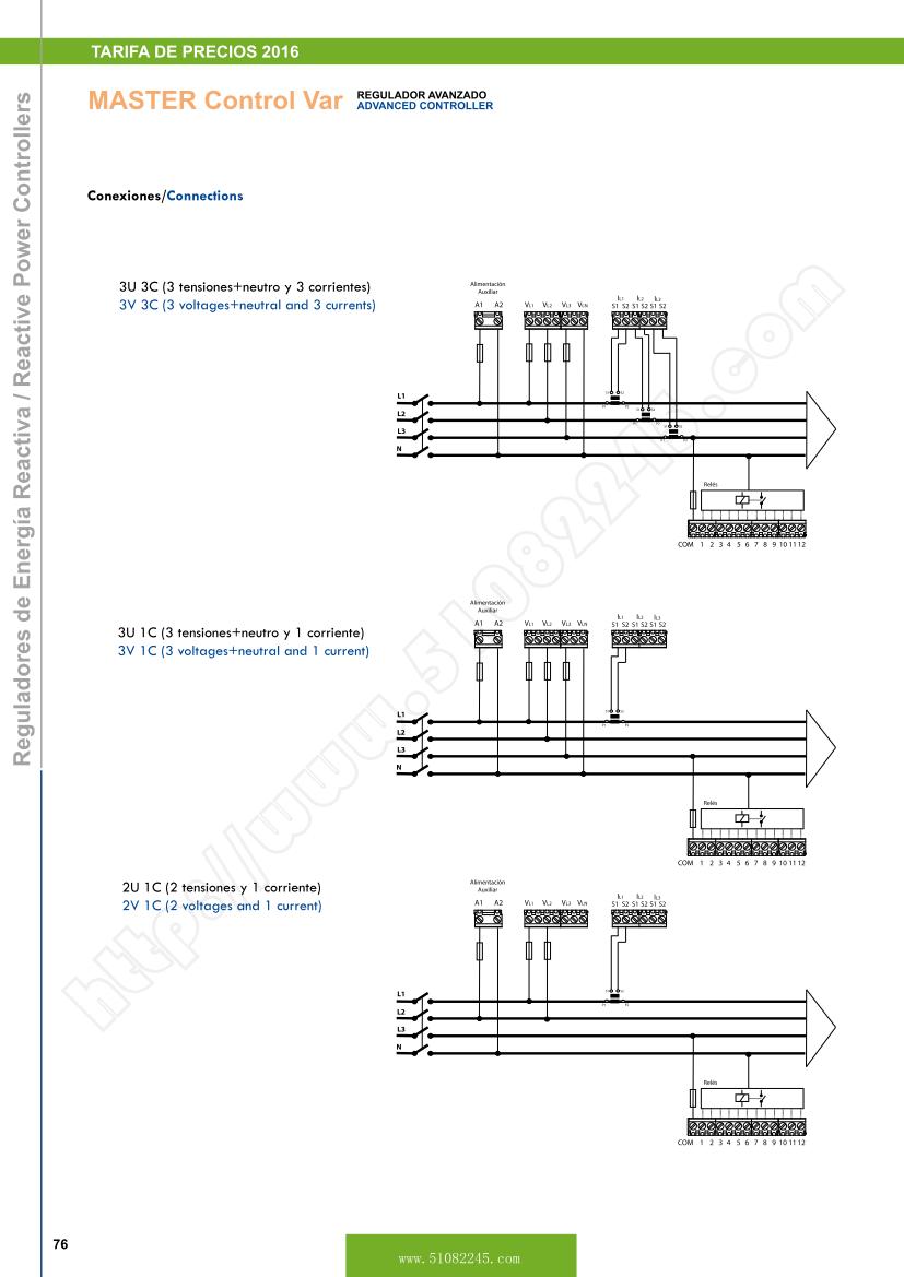
MASTER Control Var ADVANCED CONTROLLER
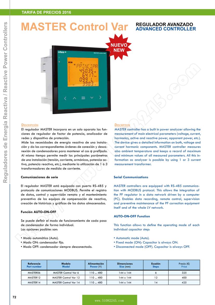
Description
MASTER controller has a built in power analyzer allowing the measurement of main electrical parameters (voltage, current, harmonics, active and reactive power, apparent power, etc.). The device gives a detailed information on both, voltage and current harmonic components. MASTER controller measures also ambient temperature and keeps a record of maximum and minimum values of all measured parameters. All this information as analyzer is possible by using 1 or 3 current measurement transformer.
Serial Communications
MASTER controllers are equipped with RS-485 communication with MODBUS protocol. This allows the integration of the PF regulator in a data network driven by a computer
(PC). Enables data recording, remote control, supervision and preventive maintenance of the PF correction equipment itself and of the whole LV network.
AUTO-ON-OFF Function
This function allows to define the operating mode of each individual capacitor step:
Automatic mode (Auto).
Fixed mode (ON): Capacitor is always ON.
Disconnected mode (OFF). Capacitor is always OFF.
Part number |
Model |
Power (V) |
Size (mm) |
Steps |
Price(�) |
MASTER06 |
MASTER Control Var 6 |
110��480 |
144x144 |
6 |
325 |
MASTER12 |
MASTER Control Var 12 |
110��480 |
144x144 |
12 |
400 |
MASTER14 |
MASTER Control Var 14 |
110��480 |
144x144 |
14 |
425 |
Plug and Play
A series of parameters must be configured when a power factor regulator is installed, to make sure that it operates correctly. Some of these parameters might be hard to know, such as, for example, the voltage phases or the voltage corresponding to the current measured, as well as the current transformer ratio. MASTER has been designed with a smart automatic process that detects the necessary parameters, such as:
C/K: calculates the ratio of the current transformer and the power of the smallest step.
Phase: Identifies the voltage sequence and correspondence with current. In other words, it identifies the UL1, UL2, UL3, when the current measured is IL1, IL2, I
L3 and whether it is connected in the opposite way or not.
Number of stages installed and Program: The system connects all stages in a sequence, finds out how many stages are installed and then calculates the program,
i.e., the power ratio of the capacitors.
Built-in leakage control
MASTER have a built-in circuit to measure the earth leakage current through a WGC transformer. The regulator is able to measure the individual leakage of each capacitor. This allows to disable a damaged capacitor if an excess of leakage current is detected without interrupting the supply service.
Safety and maintenance
MASTER performs a capacitor test every time that a capacitor step is switched ON. The real power and the leakage current of each step can be displayed.
Up to 14 different alarm conditions can be programmed.
Internal counter register which counts the number of operations of each individual capacitor step
Digital inputs
Digital outputs
Fan relay with internal sensor for forced ventilation
Set up of 4 different cos �� for compensation in different time periods
Suitable for medium voltage automatic capacitor banks
Note: Version for static switches with thyristors (on request)
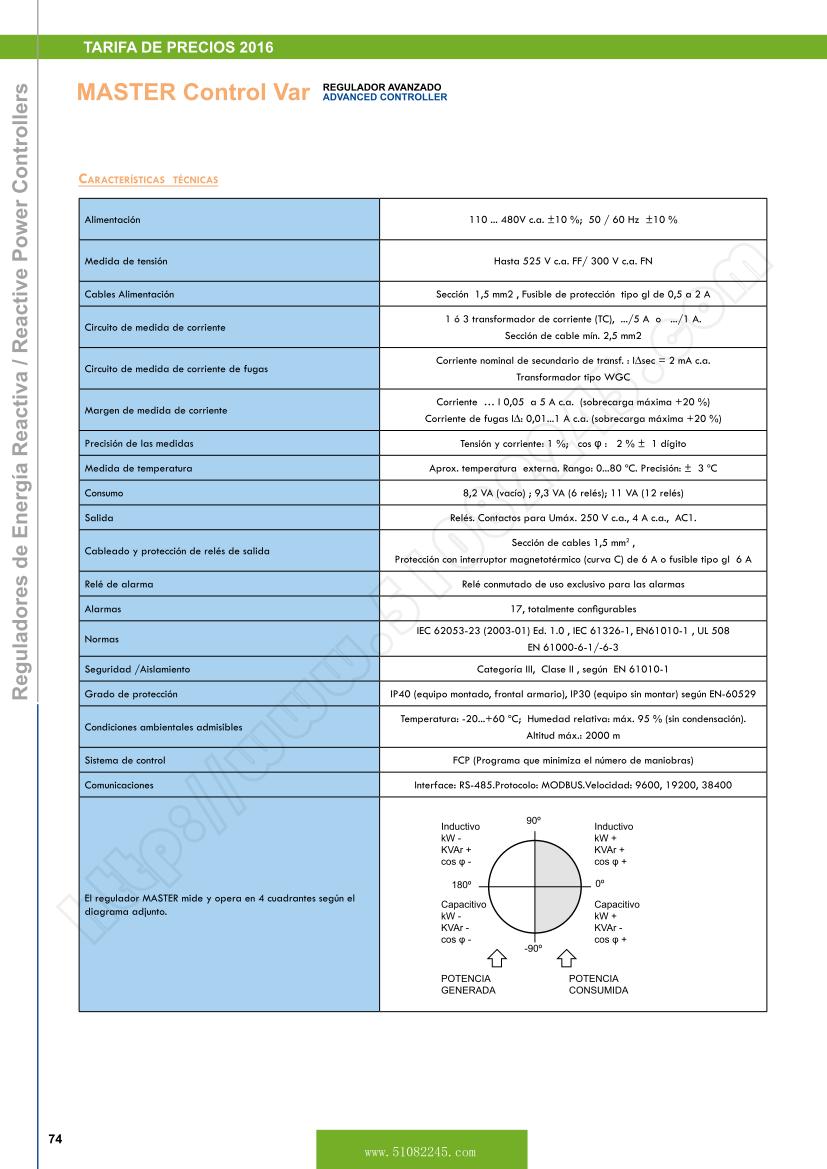
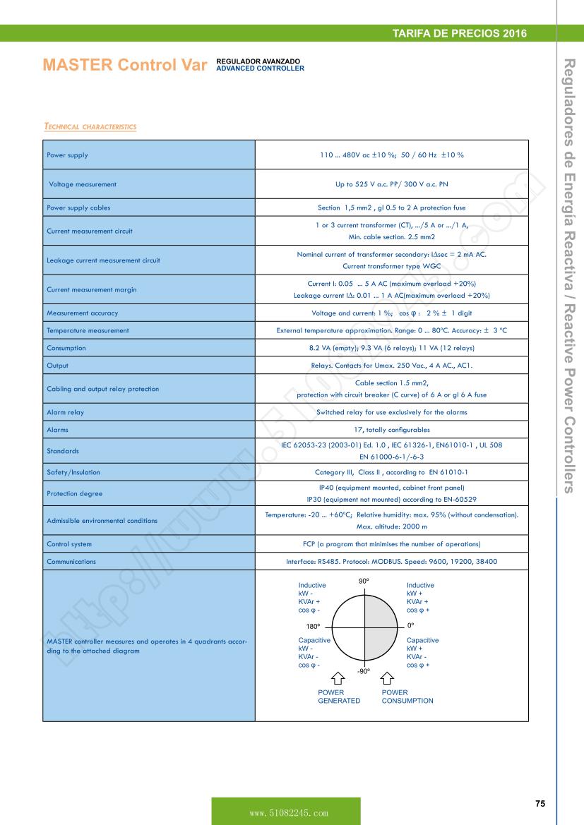
Technical Characteristics
| Power supply |
110 ... 480V ac ��10 %; 50 / 60 Hz ��10 % |
| Voltage measurement |
Up to 525 V a.c. PP/ 300 V a.c. PN |
| Power supply cables |
Section 1,5 mm2 , gl 0.5 to 2 A protection fuse |
| Current measurement circuit |
1 or 3 current transformer (CT), .../5 A or .../1 A,
Min. cable section. 2.5 mm2 |
| Leakage current measurement circuit |
Nominal current of transformer secondary: Isec = 2 mA AC.
Current transformer type WGC |
| Current measurement margin |
Current I: 0.05 ... 5 A AC (maximum overload +20%)
Leakage current I: 0.01 ... 1 A AC(maximum overload +20%) |
| Measurement accuracy |
Voltage and current: 1 %; cos �� : 2 % �� 1 digit |
| Temperature measurement |
External temperature approximation. Range: 0 ... 80oC. Accuracy: �� 3 oC |
| Consumption |
8.2 VA (empty); 9.3 VA (6 relays); 11 VA (12 relays) |
| Output |
Relays. Contacts for Umax. 250 Vac., 4 A AC., AC1. |
| Cabling and output relay protection |
Cable section 1.5 mm2,
protection with circuit breaker (C curve) of 6 A or gl 6 A fuse |
| Alarm relay |
Switched relay for use exclusively for the alarms |
| Standards |
/-6-3 |
| Safety/Insulation |
Category III, Class II , according to |
| Protection degree |
(equipment mounted, cabinet front panel)
IP30 (equipment not mounted) according to |
| Admissible environmental conditions |
Temperature: -20 ... +60oC; Relative humidity: max. 95% (without condensation). Max. altitude: 2000 m |
| Control system |
FCP (a program that minimises the number of operations) |
| Communications |
Interface: RS485. Protocol: MODBUS. Speed: 9600, 19200, 38400 |
Reactive Power Controllers
Description
Reactive power controllers MCE ADV, PFCL and MASTER are designed to measure the reactive power of an installation and to give the necessary instructions for connecting and disconnecting capacitors in order to maintain the desired cos �� .
All the controllers are commanded by a microprocessor that ensures an uniform ageing of contactors and capacitors by using a circular connection sequence that takes into account the time that each capacitor has been switched on.
Power factor value to be reached can be adjusted in a continuous way, between 0.85 inductive and 0.95 capacitive.
Standard working programs for controllers are 1:1:1:1,
1:2:2:2, 1:2:4:4, 1:2:4:8 and 1:1:2:2.
Advantages
Uniform ageing of the capacitors and contactors
High speed operation with less number of switchings
True rms measuring circuit, insensitive to harmonics
Automatic disconnection of all the capacitors in the case of
a failure in the electrical network
Detection and automatic indication of current transformer
wrongly connected
Digital cos �� display
Adjustable operation delay
Power factor alarm relay (PFCL/MASTER)
Harmonic distortion alarm relay (PFCL/MASTER)
Some others advanced features, depending on the model.
Range
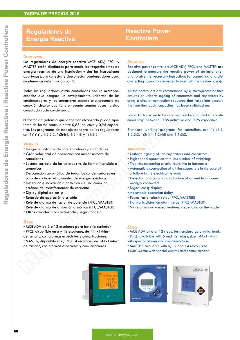
MCE ADV, of 6 or 12 steps, for standard automatic bank.
PFCL, available with 6 and 12 relays, size 144x144mm with special alarms and communication.
MASTER, available with 6, 12 and 14 relays, size 144x144mm with special alarms and communication.
|
|